

I live in the pacific northwest, where blackberries are delicious, yet noxious in their spikey unpleasantness. Because I enjoy the delicious side of this satanic vine, I also have to deal with the noxious side. Also because boredom, I decided to convert the BXpanded backhoe thumb on my 1025R 260 backhoe from manual to hydraulic to ease in the task of pulling and gathering the vines for transport to their fiery demise. And it's good for so many other things. They say the 1025R is a toy, so I figure I might as well play with it.
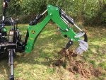
Cutting to the chase for those who are just curious, here are a few pics of the result. Read on for further details on how this was accomplished.
![]()
![]()
![]()
![]()
![]()
Parts
The total cost of the conversion (parts purchased July 2017) is around $450. Nearly all of the parts were acquired through surpluscenter.com, with the exception of the diverter valve (eBay), 45 degree elbows (eBay), and the hose sleeving (Amazon).
You'll also need some long 1/4-20 or similar bolts and nuts for the diverter mount, and a 3/4-10 (or 3/4-16) x 6" Grade 8 bolt. You'll also need to reuse the grad 8 bolt that came with the thumb. These two bolts mount each end of the cylinder to the thumb mounting plates. There's enough power to bend a non-grade 8 bolt, so although they're much more expensive, go with grade 8. I found this at my local hardware store (I happen to have a good small-chain store close by) for $8.50.
Oh, and primer and paint. Deere green and blitz black, of course.
General Description of the project
You'll need basic welding skills for the quick connector mount, diverter valve mount, and hose mount. The 96" hoses are routed between the control box and the quick connectors mounted to the stick through the boom. The quick connector mount on the stick was fabricobbled from some black iron pipe and a piece of scrap rod, cut at ~50 degrees and welded back together. This is a place where you'll be improvising.
You won't be able to use the existing hole in the thumb where the manual adjuster is mounted. You'll need to drill new .75" holes. For this, start by using a long drill bit that can go through both thumb plates (see photo), preferably done on a drill press. Then you can work up to the .75" hole on each side independently. Where you drill this hole will take some experimentation. I made a cardboard template, but I didn't keep it, so you'll need to figure this part out. I included a photo from the side, which you may be able to use as a very rough guide. To figure out where to drill the hole, with the elbows installed on the cylinder, retract the cylinder completely, then mount it to the stick. Pull the thumb all the way back to the maximum retracted position. Choose this carefully, ensuring you'll have clearance for elbows and hoses on the cylinder when doing this hydraulically. Use your method of choice to mark the thumb where the thumb side of the cylinder mount lines up. Transfer this mark to the outside. Check and adjust this mark no less than 10 times before drilling. Once drilled, it's a really hard step to undo.
You'll also want to weld some stops to the thumb using some scrap steel. See photo. This ensures the thumb can't be pulled back into any vital hydraulics.
The diverter valve was mounted to rear of the control box using some 1.5" angle iron ground in some strategic places. Mount up the elbows to the valve, then drill and mount the angle iron to the valve so that you can trial fit and mark the control box for final location. Mark the mount locations for the angle iron after ensuring that the boom cannot make contact with the valve throughout its full range of motion. Once confident in the position, remove the angle from the valve and tack weld to the control box. Double check clearances before fully welding. See photos. Note that the connector for the diverter needs to be off to the side in order to clear the boom. See the final picture of the valve above.
The rest of the project is routing hoses, threading and tightening elbows and couplers and whatnot, and wiring the valve's solenoid to the button on the stick control and ultimately to the ignition. I used a standard SAE power connector (like you'd find on a battery tender) for the power wire for backhoe removal. I won't go into details of the wiring. See pictures for coupler locations.
Pictorial
Note that the BB software automatically shows photo previews in landscape. Sorry.
![]()
"The Kit" - Most of the parts from surpluscenter.com. Cylinder was back-ordered, so it came separately.
![]()
Tacking the diverter mounts. Triple check the diverter mounting spot for clearance when boom is fully retracted and at full left and full right.
![]()
Diverter mount ready for cleaning.
![]()
![]()
![]()
Details of diverter elbows and routing. Note that the upper left and upper right elbows are threaded into straight adapters to add some length to clear the lower elbows. The left side of the valve is inputs from the control block (stick control) to the diverter via 12" hoses. The middle ports go to the thumb via the 96" hoses, and the right ports go to the existing stick lines. Note that the solenoid needs to be turned 90 degrees so that the connector clears the boom. This isn't shown in this photo, but is in the photo up top.
Cutting to the chase for those who are just curious, here are a few pics of the result. Read on for further details on how this was accomplished.


Parts
The total cost of the conversion (parts purchased July 2017) is around $450. Nearly all of the parts were acquired through surpluscenter.com, with the exception of the diverter valve (eBay), 45 degree elbows (eBay), and the hose sleeving (Amazon).
| Desc | Part # (Source) | QTY | USD Price each (July 2017) | Notes |
| 1.5x6x.75 DA Hydraulic Cylinder | 9-4410-06 (Surpluscenter.com) | 1 | 95.55 | 1.5" bore, 6" stroke, .75" rod, 2000 PSI, 11.5" retracted length, .75" mount |
| Hydraulic solenoid operated selector diverter valve 12 volt DC | (eBay - industrialsales719) | 1 | 128 | 12 volt DC voltage. #8 SAE o-ring boss ports. 13.2 GPM @ 3600 PSI. 2.5 amps. -4 degrees to +158 degrees F working temperature. Six ports, supply, return and four work ports. Does not require an additional case drain line. |
| 1/4" x 96" JIC 6F Swivel x JIC 6F Swivel SAE 100R16 Hydraulic Hose Assembly 5800 PSI | 921-2296 (Surpluscenter.com) | 1 | 20.95 | Routed valve work ports through boom to quick connects. |
| 1/4" x 24" JIC 6F Swivel x JIC 6F Swivel SAE 100R16 Hydraulic Hose | 921-2224 (Surpluscenter.com) | 2 | 9.70 | Routed from quick connects to cylinder 45 degree JIC elbow |
| 1/4" x 12" JIC 6F Swivel x JIC 6F Swivel SAE 100R16 Hydraulic Hose Assembly 5800 PSI | 921-2212 (Surpluscenter.com) | 4 | 7.50 | Connects diverter to control block, and diverter to original stick hoses |
| 1/4 in Two Wire Dual Hydraulic Hose Clamp | 9-A2-14-D (Surpluscenter.com) | 1 | 3.45 | Welded to thumb mount plate. See pictures |
| 1/4" NPT ISO 7241-B Quick Disconnect Hydraulic Couplings / Couplers | (eBay – summit-hydraulics) | 2 sets | 39.95 for 4 sets | Price for 4 set combo, only 2 set needed. |
| Apache 39020518 1.59" ID x 15 -Feet, Nylon Protective Hose Sleeve | Apache 39020518 (Amazon) | 1 | 19.00 | Protects 96” hose through boom and at pivots. Both hoses fit together in this sleeve. More than enough is included with purchase. |
| Apache 39020508 1.14" ID x 15 -Feet, Nylon Protective Hose Sleeve | Apache 39020508 (Amazon) | 1 | 13.54 | Protects 24” hose around stick, and 12" hoses at controls. More than enough is included with purchase. |
| SAE 8M To SAE 6F Adapter | 9-6410-8-6 (Surpluscenter.com) | 2 | 2.15 | Converts valve both upper-side input and output ports, and extends them out to clear the ports underneath. See photos. |
| JIC 6M x SAE 6M 90 Elbow | 9-6801-6-6 (Surpluscenter.com) | 2 | 2.20 | Elbow that goes on the SAE-8M to SAE-6F straight adapters, on the upper-side input and output ports of the diverter. |
| JIC 6M x SAE 8M 90 Elbow | 9-6801-6-8 (Surpluscenter.com) | 4 | 2.20 | Elbow that adapts lower-side input and output ports, and the middle work ports of the divert valve. |
| JIC 6M x 1/4 NPTM Connector | 9-2404-6-4 (Surpluscenter.com) | 4 | 1.25 | Adapts 96” JIC hose to fit the quick connectors on the stick. |
| JIC 6M x 3/8 NPTM 90 Elbow | 9-2501-6-6 (Surpluscenter.com) | 2 | 2.60 | Elbow at hydraulic cylinder |
| 6502-06-06 3/8" Male JIC X 3/8" Female JIC 45 45-degree elbow | 6502-06-06 (eBay - rnlhydraulics) | 2 | 5.75 | 45 degree elbow to clear cylinder ports and thumb. See pictures. |
| K&S Technologies 12-0101 Honda CR Style Engine Kill Switch | 12-0101 (Amazon) | 1 | ||
| Total | 443.50 | Calculated using $10 per set for quick connects. Does not include cost of the BXPanded thumb ($350.00 as of Feb 2019) |
You'll also need some long 1/4-20 or similar bolts and nuts for the diverter mount, and a 3/4-10 (or 3/4-16) x 6" Grade 8 bolt. You'll also need to reuse the grad 8 bolt that came with the thumb. These two bolts mount each end of the cylinder to the thumb mounting plates. There's enough power to bend a non-grade 8 bolt, so although they're much more expensive, go with grade 8. I found this at my local hardware store (I happen to have a good small-chain store close by) for $8.50.
Oh, and primer and paint. Deere green and blitz black, of course.
General Description of the project
You'll need basic welding skills for the quick connector mount, diverter valve mount, and hose mount. The 96" hoses are routed between the control box and the quick connectors mounted to the stick through the boom. The quick connector mount on the stick was fabricobbled from some black iron pipe and a piece of scrap rod, cut at ~50 degrees and welded back together. This is a place where you'll be improvising.
You won't be able to use the existing hole in the thumb where the manual adjuster is mounted. You'll need to drill new .75" holes. For this, start by using a long drill bit that can go through both thumb plates (see photo), preferably done on a drill press. Then you can work up to the .75" hole on each side independently. Where you drill this hole will take some experimentation. I made a cardboard template, but I didn't keep it, so you'll need to figure this part out. I included a photo from the side, which you may be able to use as a very rough guide. To figure out where to drill the hole, with the elbows installed on the cylinder, retract the cylinder completely, then mount it to the stick. Pull the thumb all the way back to the maximum retracted position. Choose this carefully, ensuring you'll have clearance for elbows and hoses on the cylinder when doing this hydraulically. Use your method of choice to mark the thumb where the thumb side of the cylinder mount lines up. Transfer this mark to the outside. Check and adjust this mark no less than 10 times before drilling. Once drilled, it's a really hard step to undo.
You'll also want to weld some stops to the thumb using some scrap steel. See photo. This ensures the thumb can't be pulled back into any vital hydraulics.
The diverter valve was mounted to rear of the control box using some 1.5" angle iron ground in some strategic places. Mount up the elbows to the valve, then drill and mount the angle iron to the valve so that you can trial fit and mark the control box for final location. Mark the mount locations for the angle iron after ensuring that the boom cannot make contact with the valve throughout its full range of motion. Once confident in the position, remove the angle from the valve and tack weld to the control box. Double check clearances before fully welding. See photos. Note that the connector for the diverter needs to be off to the side in order to clear the boom. See the final picture of the valve above.
The rest of the project is routing hoses, threading and tightening elbows and couplers and whatnot, and wiring the valve's solenoid to the button on the stick control and ultimately to the ignition. I used a standard SAE power connector (like you'd find on a battery tender) for the power wire for backhoe removal. I won't go into details of the wiring. See pictures for coupler locations.
Pictorial
Note that the BB software automatically shows photo previews in landscape. Sorry.

"The Kit" - Most of the parts from surpluscenter.com. Cylinder was back-ordered, so it came separately.

Tacking the diverter mounts. Triple check the diverter mounting spot for clearance when boom is fully retracted and at full left and full right.

Diverter mount ready for cleaning.


Details of diverter elbows and routing. Note that the upper left and upper right elbows are threaded into straight adapters to add some length to clear the lower elbows. The left side of the valve is inputs from the control block (stick control) to the diverter via 12" hoses. The middle ports go to the thumb via the 96" hoses, and the right ports go to the existing stick lines. Note that the solenoid needs to be turned 90 degrees so that the connector clears the boom. This isn't shown in this photo, but is in the photo up top.
")


