This forum has been extremely helpful to me in many ways while acquiring my 2520 and I thought I would try and give back a little.
Before I get started a lot of background info to do this was collected off this forum and most of it came from KennyD in one post or another.
I just really wanted to put together a consolidated list of parts to do PB on a 2520. I am very happy how this came out and I think I have about $65 into it instead of the $300 kit from Deere. Maybe this will help some folks save some money.
Parts List from Deere:
PT13744 John Deere Plug
M808060 John Deere Label (In/Out Sticker - Very Optional)
Hydraulic Parts (I am going to put these in the order of hydraulic flow starting from the "Out" port on the tractor hydraulic block and ending on the "In" port of the hydraulic block):
90 Elbow, 3/8" JIC x #6 SAE/ORB (Steel)
3/8" X 30" JIC 6F X JIC 6F Hydraulic Hose
3/8" NPTF Male x 3/8" JIC Bulkhead (Steel)
3/8" Hydraulic Quick Disconnect Set ISO Series B NPTF (Steel)
90 Elbow, 3/8" JIC x 3/8" NPTF Male (Steel)
3/8" X 12" JIC 6F X JIC 6F Hydraulic Hose
90 Elbow, 3/8" JIC Male x 3/8" JIC Female Swivel (Steel)
3/8" JIC x 3/8" JIC Bulkhead Union with Locknut (Steel)
3/8" X 30" JIC 6F X JIC 6F Hydraulic Hose
90 Elbow, 3/8" JIC x #6 SAE/ORB, Double Long (Steel)
I used 30" hoses because they were pre-made and cheap. They are very nice and fit very well however 27" would have been ideal. I also did it in all 3/8ths and #6 so I didn't have to adapt any sizes and that worked out well. Last my quick disconnect set on my BH46 was ISO Series B so I just went with that. Check your backhoe or if you don't have one you really can get whichever ones you want.
Step 0
Remove right rear tire from the tractor. Remove the hydraulic block from the tractor. This will require removing the two hex bolts from the loader valve and sliding the block out toward the back of the tractor (it is behind the valve). One of the banjo bolts attaching a line to the valve will need to be removed to gain access to the hex bolt.
Step 1
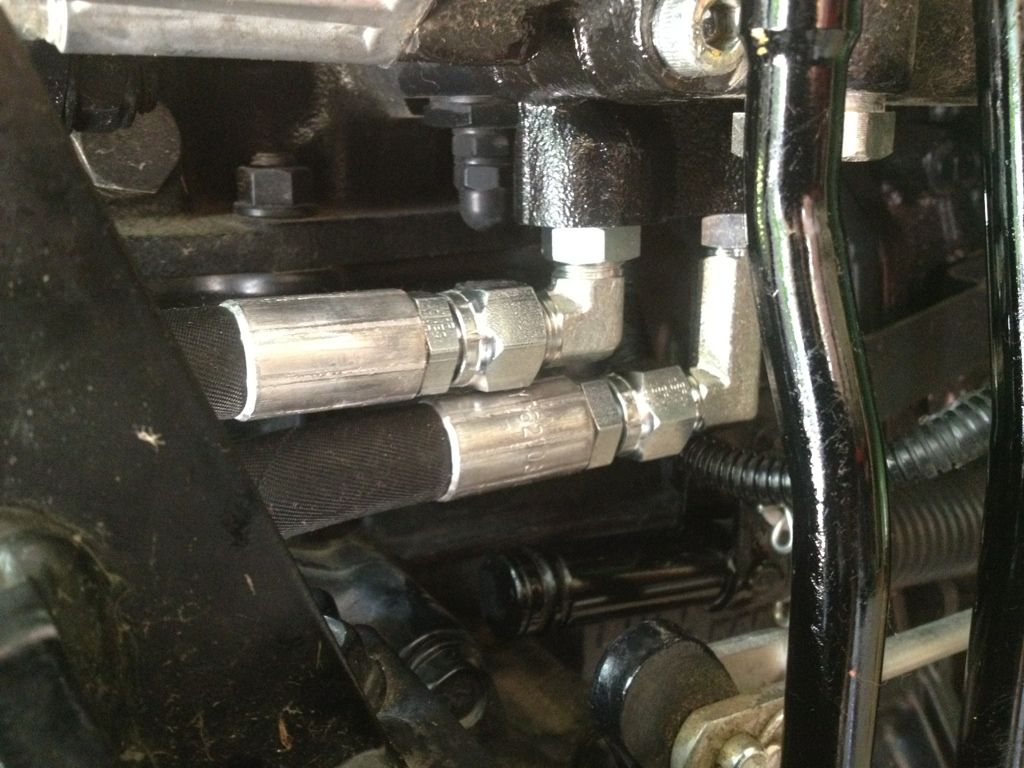
Remove the 3 caps from the hydraulic block. Insert the plug (PT13744) through the opening and reinstall the cap. In the "Out" port install the 90 Elbow, 3/8" JIC x #6 SAE/ORB fitting then connect the 30" hose to that. Next install the 90 Elbow, 3/8" JIC x #6 SAE/ORB, Double Long fitting in the "In" port and attach a 30" hose to that.
![Image]()
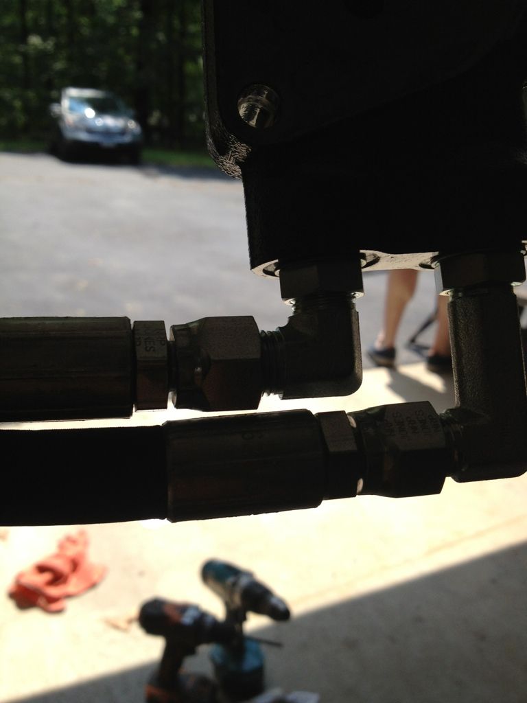
The normal 90 and double long 90 fit perfect. It looks tight but there is an air gap. To get them to fit you have to install in the order above.
![Image]()
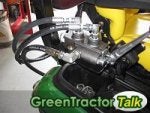
Step 2
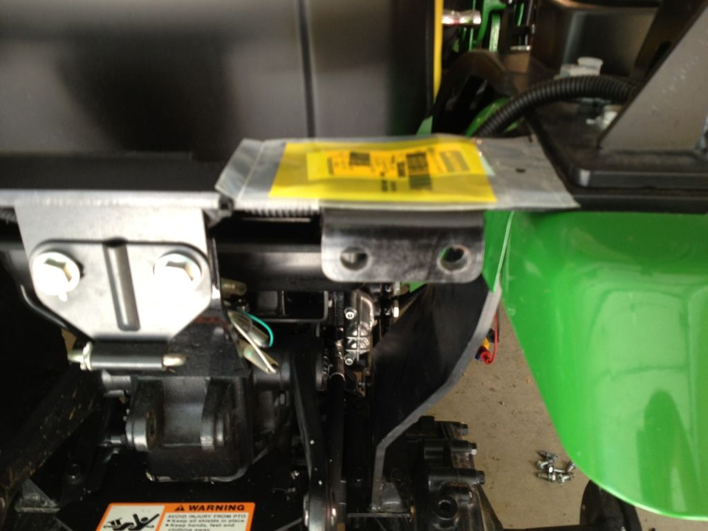
Put the block back in the tractor, install hex bolts and banjo fitting.
![Image]()
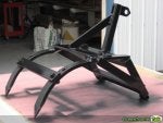
Step 3
Drill out the bracket on the back of the tractor to fit the bulkhead connectors. I am not sure what this was intended for by Deere but it works great for this.Install bulkheads and connect 30" hoses to them under the bracket. Install the NPT bulkhead in the hole near the fender and the JIC one toward the middle of the tractor.
![Image]()
Step 4
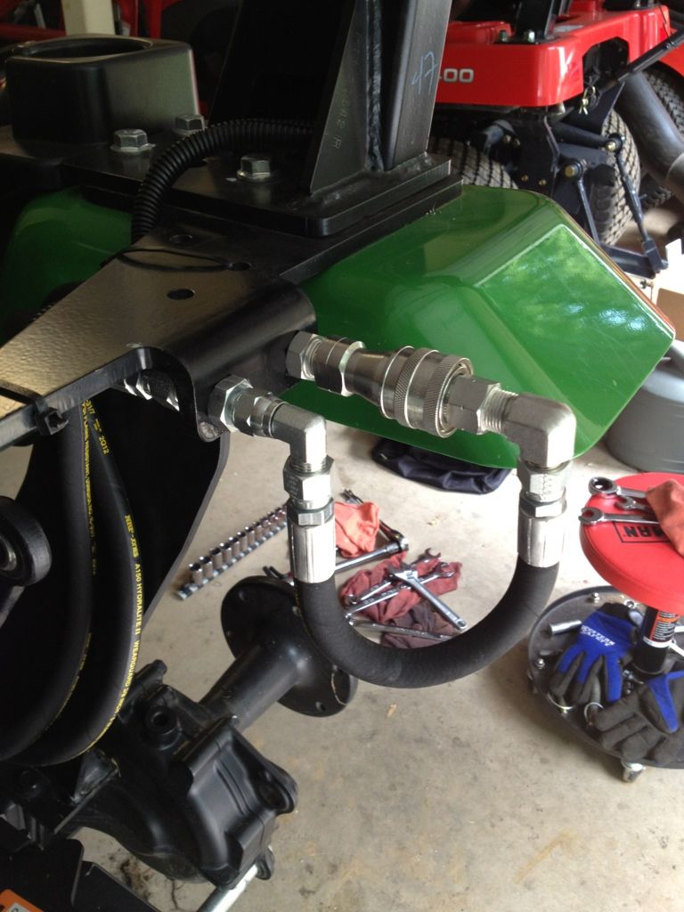
Attach the female quick disconnect to the NPT bulkhead (Use proper sealant). Attach the 90 Elbow, 3/8" JIC x 3/8" NPT Male fitting to the male quick disconnect (use proper sealant). Attach the 12" hose and then use the 90 Elbow, 3/8" JIC Male x 3/8" JIC Female Swivel to attach to the JIC bulkhead.
![Image]()
Step 5
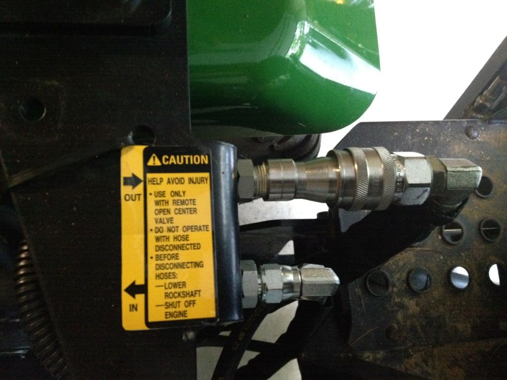
Add decal M808060 to make it look more factory.
![Image]()
All in all it works great. The only thing I am going to keep an eye out for is a shorter female quick disconnect so it protrudes less.
Is it is OK to post I purchased the hoses from Surplus Center and The fittings from Discount Hydraulic Hose.
Before I get started a lot of background info to do this was collected off this forum and most of it came from KennyD in one post or another.
I just really wanted to put together a consolidated list of parts to do PB on a 2520. I am very happy how this came out and I think I have about $65 into it instead of the $300 kit from Deere. Maybe this will help some folks save some money.
Parts List from Deere:
PT13744 John Deere Plug
M808060 John Deere Label (In/Out Sticker - Very Optional)
Hydraulic Parts (I am going to put these in the order of hydraulic flow starting from the "Out" port on the tractor hydraulic block and ending on the "In" port of the hydraulic block):
90 Elbow, 3/8" JIC x #6 SAE/ORB (Steel)
3/8" X 30" JIC 6F X JIC 6F Hydraulic Hose
3/8" NPTF Male x 3/8" JIC Bulkhead (Steel)
3/8" Hydraulic Quick Disconnect Set ISO Series B NPTF (Steel)
90 Elbow, 3/8" JIC x 3/8" NPTF Male (Steel)
3/8" X 12" JIC 6F X JIC 6F Hydraulic Hose
90 Elbow, 3/8" JIC Male x 3/8" JIC Female Swivel (Steel)
3/8" JIC x 3/8" JIC Bulkhead Union with Locknut (Steel)
3/8" X 30" JIC 6F X JIC 6F Hydraulic Hose
90 Elbow, 3/8" JIC x #6 SAE/ORB, Double Long (Steel)
I used 30" hoses because they were pre-made and cheap. They are very nice and fit very well however 27" would have been ideal. I also did it in all 3/8ths and #6 so I didn't have to adapt any sizes and that worked out well. Last my quick disconnect set on my BH46 was ISO Series B so I just went with that. Check your backhoe or if you don't have one you really can get whichever ones you want.
Step 0
Remove right rear tire from the tractor. Remove the hydraulic block from the tractor. This will require removing the two hex bolts from the loader valve and sliding the block out toward the back of the tractor (it is behind the valve). One of the banjo bolts attaching a line to the valve will need to be removed to gain access to the hex bolt.
Step 1
Remove the 3 caps from the hydraulic block. Insert the plug (PT13744) through the opening and reinstall the cap. In the "Out" port install the 90 Elbow, 3/8" JIC x #6 SAE/ORB fitting then connect the 30" hose to that. Next install the 90 Elbow, 3/8" JIC x #6 SAE/ORB, Double Long fitting in the "In" port and attach a 30" hose to that.
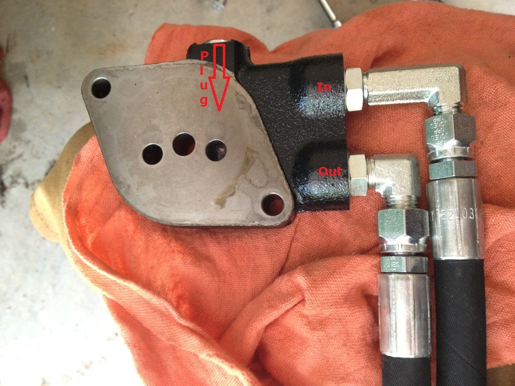
The normal 90 and double long 90 fit perfect. It looks tight but there is an air gap. To get them to fit you have to install in the order above.
Step 2
Put the block back in the tractor, install hex bolts and banjo fitting.
Step 3
Drill out the bracket on the back of the tractor to fit the bulkhead connectors. I am not sure what this was intended for by Deere but it works great for this.Install bulkheads and connect 30" hoses to them under the bracket. Install the NPT bulkhead in the hole near the fender and the JIC one toward the middle of the tractor.
Step 4
Attach the female quick disconnect to the NPT bulkhead (Use proper sealant). Attach the 90 Elbow, 3/8" JIC x 3/8" NPT Male fitting to the male quick disconnect (use proper sealant). Attach the 12" hose and then use the 90 Elbow, 3/8" JIC Male x 3/8" JIC Female Swivel to attach to the JIC bulkhead.
Step 5
Add decal M808060 to make it look more factory.
All in all it works great. The only thing I am going to keep an eye out for is a shorter female quick disconnect so it protrudes less.
Is it is OK to post I purchased the hoses from Surplus Center and The fittings from Discount Hydraulic Hose.